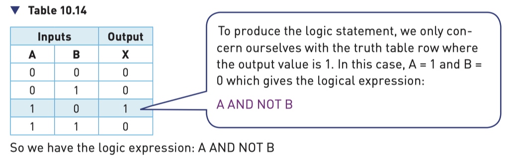
Logic Gates
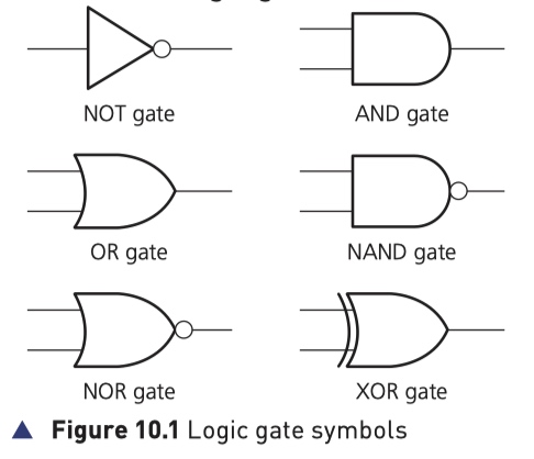
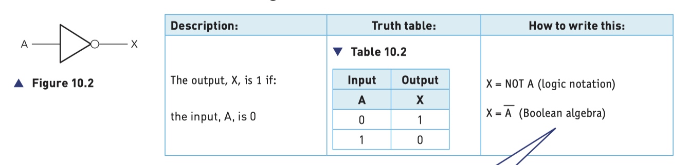
NOT Gate
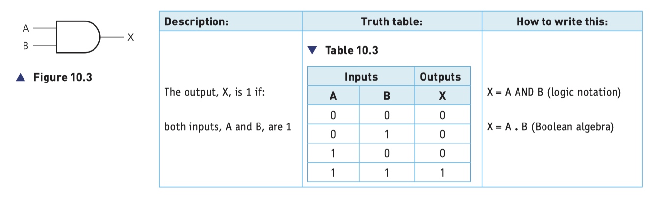
AND Gate
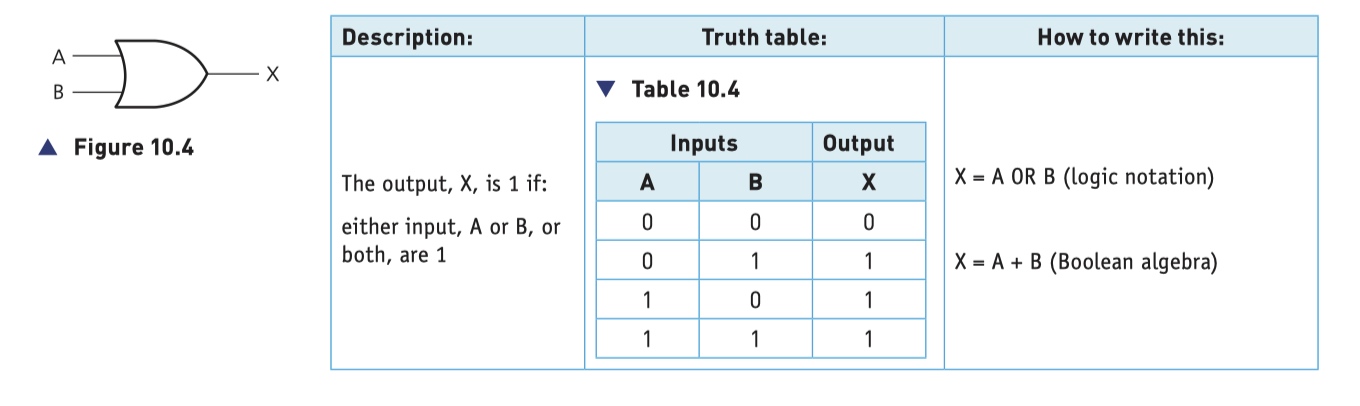
OR Gate
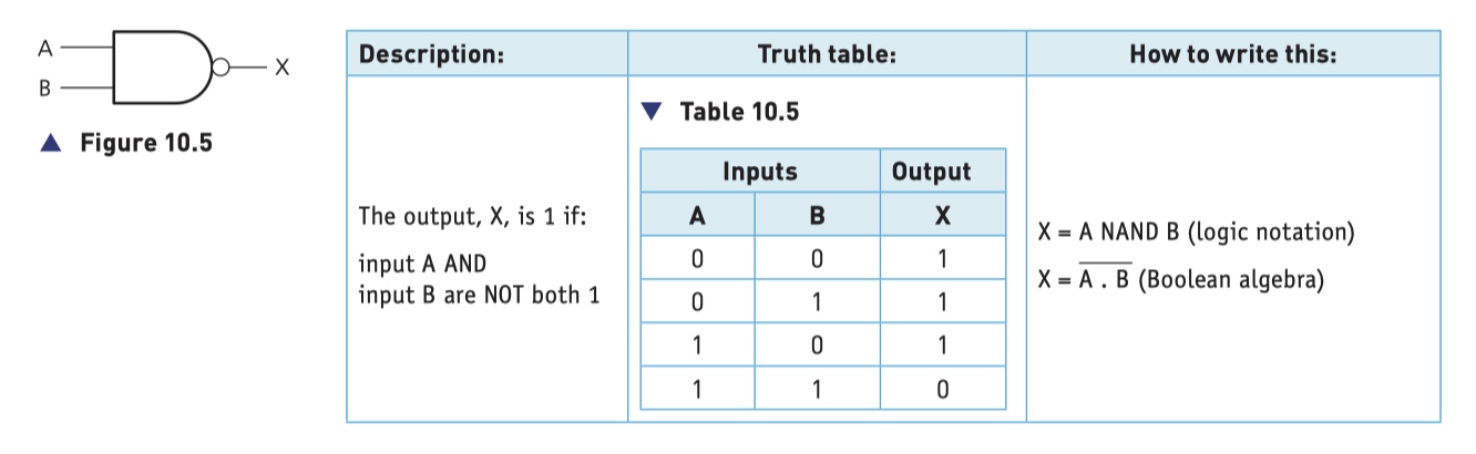
NAND Gate (NOT AND)
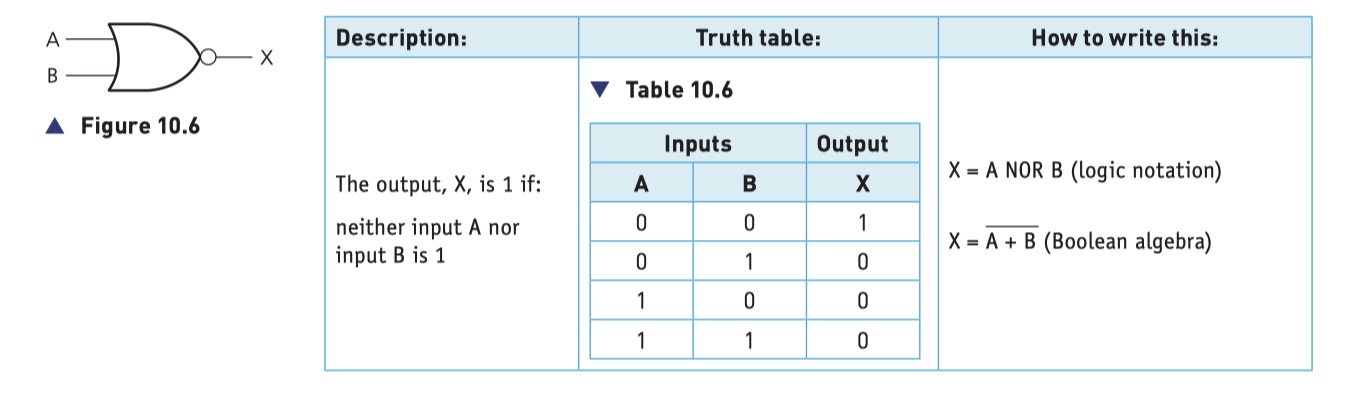
NOR Gate (NOT OR)
XOR Gate (XOR Gate)
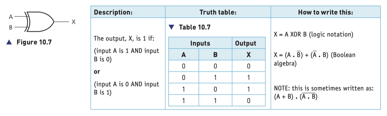
- . represents the AND operation
- + represents the OR operation
- a bar (above the letter or letters, e.g. a) represents the NOT operation.
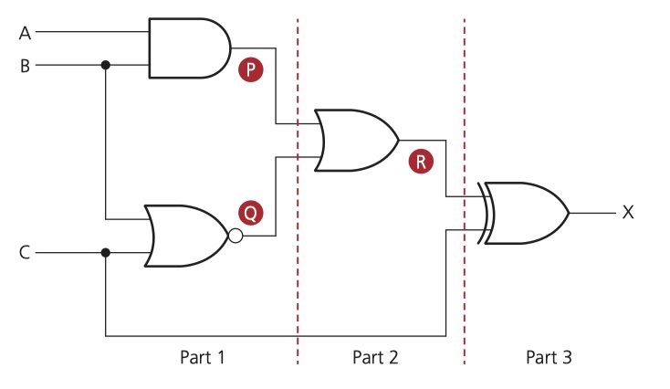
题目:找出对应逻辑图(logic circuit)的真值表(truth table)
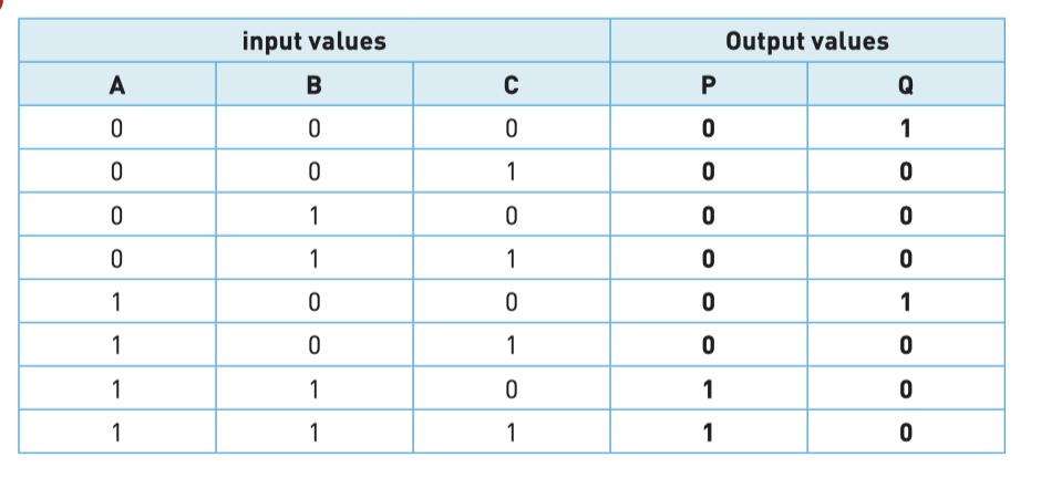
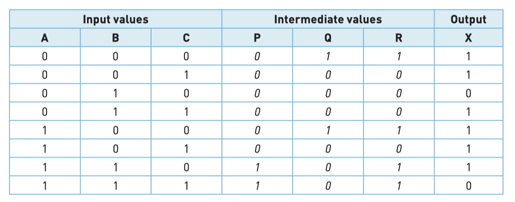
Step 1 - find the intermediate values P and Q
找出对应逻辑图(logic circuit)的真值表(truth table)
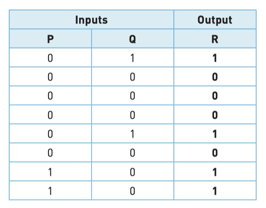
Step 2 - find intermediate values R use P and Q
找出对应逻辑图(logic circuit)的真值表(truth table)
Step 3 - find final part X use intermediate R and C
找出对应逻辑图(logic circuit)的真值表(truth table)
Final result
找出对应逻辑图(logic circuit)的真值表(truth table)
Example 1
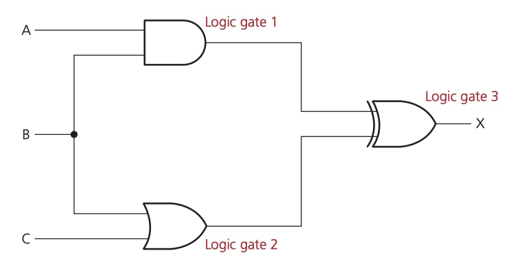
- logic gate1::
(A AND B) - logic gate2::
(B OR C) - final result::
(A AND B) XOR (B OR C)
Example 2
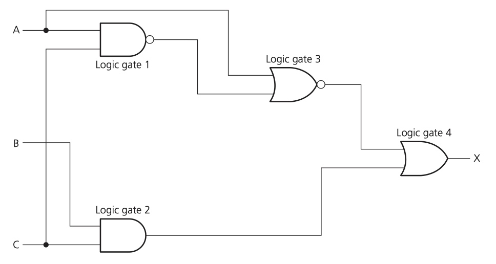
- logic gate 1::
(A NAND C) - logic gate 2::
(B AND C) - logic gate 3::
(logic gate 1) NOR A ~ ((A NAND C) NOR A) - logic gate 4::
((A NAND C) NOR A) OR (B AND C)
Example 1
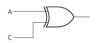
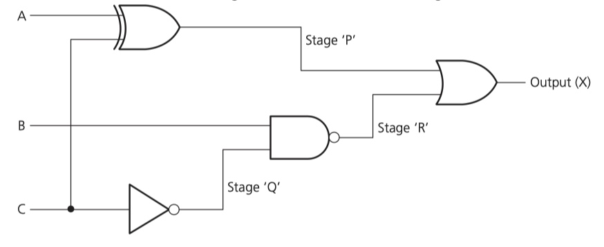
Given logic expression: (A XOR C) OR (NOT C NAND B)
first step - A XOR C
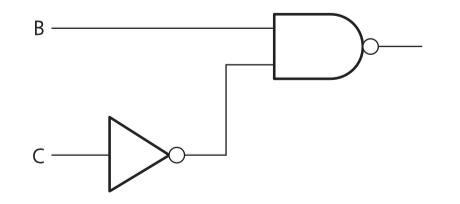
second step - NOT C NAND B
third step - combine
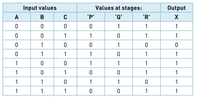
fourth step - truth table
Example 1
logic circuit
Example 2
logic circuit
Example 3
(NOT A AND NOT B AND NOT C)
(A AND NOT B AND NOT C)
(A AND B AND NOT C)
final logic expression
(NOT A AND NOT B AND NOT C)
OR (A AND NOT B AND NOT C)
OR (A AND B AND NOT C)
example 1
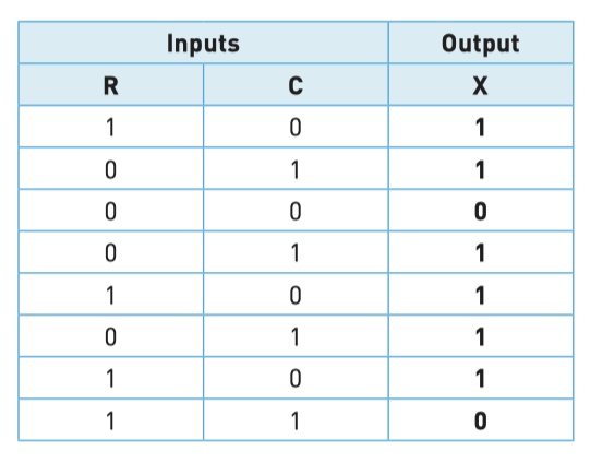
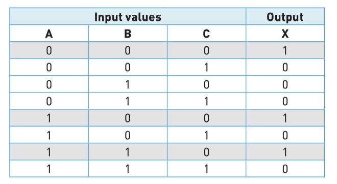
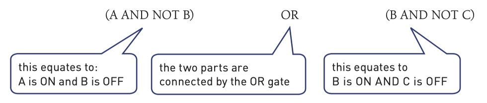
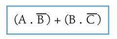
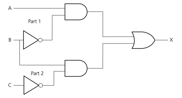
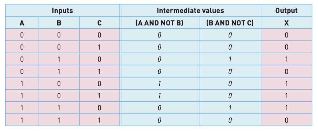
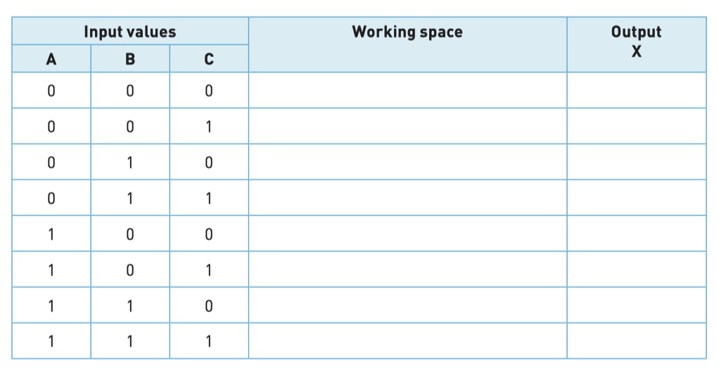
A safety system uses three inputs to a logic circuit. An alarm, X, sounds if input A represents ON and input B represents OFF; or if input B represents ON and input C represents OFF.
example 1
Consider the logic statement:
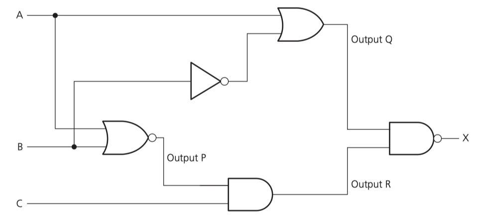
((A NOR B) AND C) NAND (A OR NOT B)
- Draw a logic circuit to represent the given logic statement.
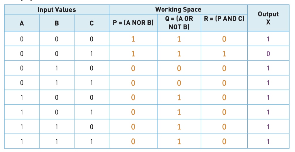
- Complete the truth table for the given logic statement.
- P = (A NOR B)
- Q = (A OR NOT B)
- R = (P AND C)