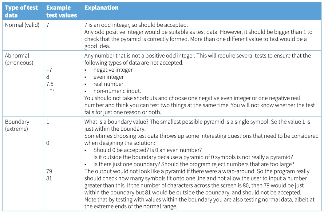
program development life cycle
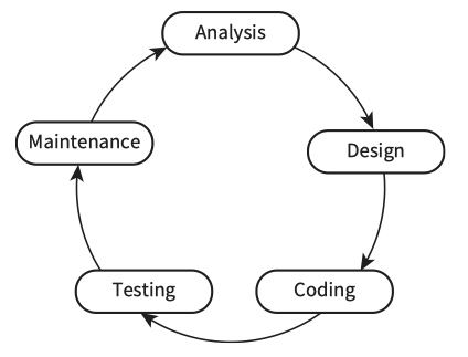
Analysis
- The first step in solving a problem is to investigate the issues and the current system if there is one. The problem needs to be defined clearly and precisely. A ‘requirements specification’ is drawn up.
- The next step is planning a solution. Sometimes there is more than one solution. You need to decide which is the most appropriate.
- The third step is to decide how to solve the problem
- bottom-up: start with a small sub-problem and then build on this
- top-down: stepwise refinement using pseudocode, flowcharts or structure charts.
Design
Plan your algorithm by drawing a flowchart or writing pseudocode.
Coding
When you have designed your solution, you might need to choose a suitable high-level programming language.
You implement your algorithm by converting your pseudocode into program code. When you start writing programs you might find it takes several attempts before the program compiles.
Testing
Only thorough testing can ensure the program really works under all circumstances
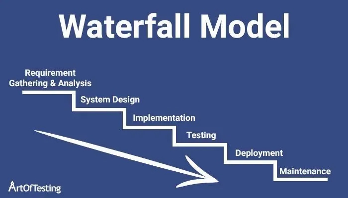
There are several different development methodologies. These include the waterfall, the iterative and the rapid application development model.
瀑布模型
瀑布模型将软件生命周期划分:制定计划、需求分析、软件设计、程序编写、软件测试和运行维护等六个基本活动,并且规定了它们自上而下、相互衔接的固定次序,如同瀑布流水,逐级下落。
在瀑布模型中,软件开发的各项活动严格按照线性方式进行,当前活动接受上一项活动的工作结果,实施完成所需的工作内容。当前活动的工作结果需要进行验证,如验证通过,则该结果作为下一项活动的输入,继续进行下一项活动,否则返回修改。
优点:严格遵循预先计划的步骤顺序进行,一切按部就班比较严谨。
- 为项目提供了按阶段分的检查点
- 当完成一个阶段后,只需要去关注后续阶段
- 可在迭代模型中应用瀑布模型
缺点:缺乏灵活性,太过线性理想化,不适合现代软件开发
- 各个阶段的划分完全固定,阶段之间产生大量的文档,极大地增加了工作量;
- 由于开发模型是线性的,用户只有等到整个过程的末期才能见到开发成果,从而增加了开发的风险;
- 早期的错误可能要等到开发后期的测试阶段才能发现,进而带来严重的后果。
- 各个软件生命周期衔接花费时间较长,团队人员交流成本大。
- 瀑布式方法在需求不明并且在项目进行过程中可能变化的情况下基本是不可行的。
迭代模型
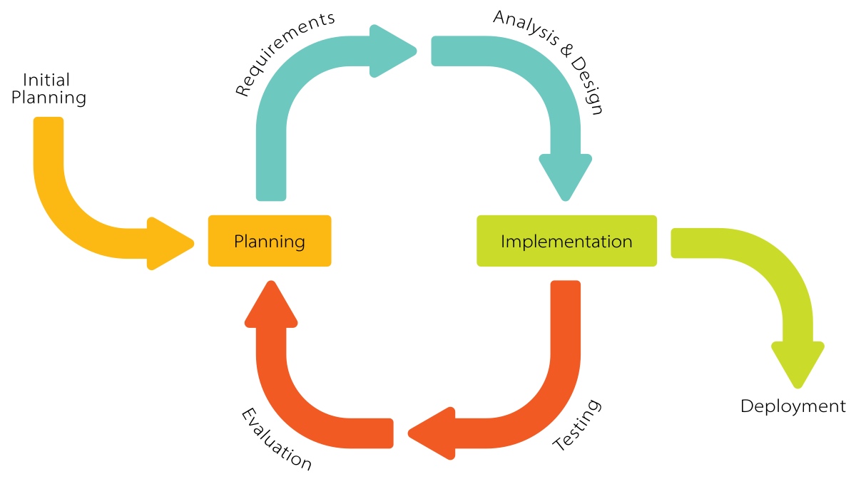
在迭代式开发方法中,整个开发工作被组织为一系列的短小的、固定长度(如3周)的小项目,被称为一系列的迭代。每一次迭代都包括了需求分析、设计、实现与测试。采用这种方法,开发工作可以在需求被完整地确定之前启动,并在一次迭代中完成系统的一部分功能或业务逻辑的开发工作。再通过客户的反馈来细化需求,并开始新一轮的迭代。
迭代和版本的区别,可理解如下:迭代一般指某版本的生产过程,包括从需求分析到测试完成;版本一般指某阶段软件开发的结果,一个可交付使用的产品。
优点:
- 降低了在一个增量上的开支风险。如果开发人员重复某个迭代,那么损失只是这一个开发有误的迭代的花费。
- 降低了产品无法按照既定进度进入市场的风险。通过在开发早期就确定风险,可以尽早来解决而不至于在开发后期匆匆忙忙。
- 加快了整个开发工作的进度。因为开发人员清楚问题的焦点所在,他们的工作会更有效率。
- 由于用户的需求并不能在一开始就作出完全的界定,它们通常是在后续阶段中不断细化的。因此,迭代过程这种模式使适应需求的变化会更容易些。因此复用性更高
快速原型模型(The Rapid Application Development (RAD) model)
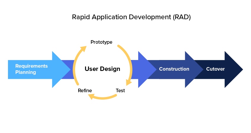
快速原型模型的第一步是建造一个快速原型,实现客户或未来的用户与系统的交互,用户或客户对原型进行评价,进一步细化待开发软件的需求。通过逐步调整原型使其满足客户的要求,开发人员可以确定客户的真正需求是什么;第二步则在第一步的基础上开发客户满意的软件产品。
显然,快速原型方法可以克服瀑布模型的缺点,减少由于软件需求不明确带来的开发风险,具有显著的效果。
快速原型的关键在于尽可能快速地建造出软件原型,一旦确定了客户的真正需求,所建造的原型将被丢弃。因此,原型系统的内部结构并不重要,重要的是必须迅速建立原型,随之迅速修改原型,以反映客户的需求。
快速原型模型有点整合“边做边改”与“瀑布模型”优点的意味。
优点:
- 生命周期短
- 整合“边做边改”与“瀑布模型”优点
- 减少软件需求不明确带来的开发风险
- 适用于小型、交互型的系统,大型系统的某些部分
缺点:
- 可能导致系统设计差、效率低、难以维护
The waterfall model
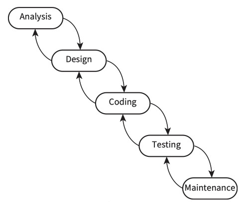
The arrows going down represent the fact that the results from one stage are input into the next stage. The arrows leading back up to an earlier stage reflect the fact that often more work is required at an earlier stage to complete the current stage.
benefits
- Simple to understand as the stages are clearly defined.
- Easy to manage due to the fixed stages in the model. Each stage has specific outcomes.
- Stages are processed and completed one at a time.
- Works well for smaller projects where requirements are very well understood.
drawbacks
- No working software is produced until late during the life cycle.
- Not a good model for complex and object-oriented projects.
- Poor model for long and ongoing projects.
- Cannot accommodate changing requirements.
- It is difficult to measure progress within stages.
- Integration is done at the very end, which doesn’t allow identifying potential technical or business issues early.
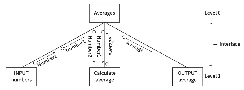
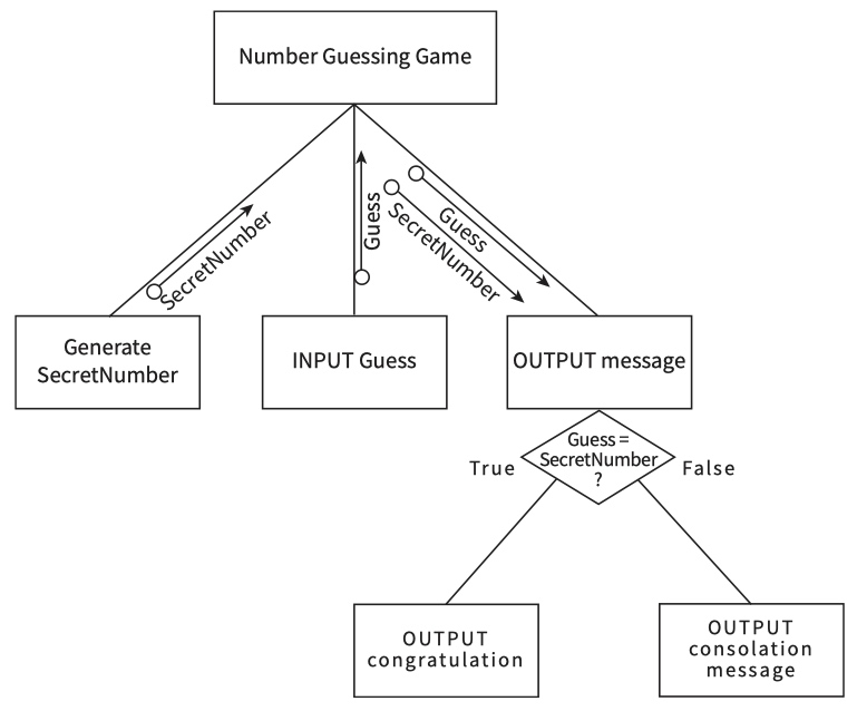
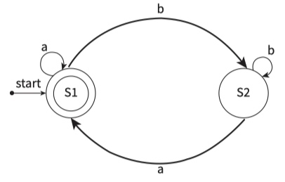
structure charts (1)
selection
repretition
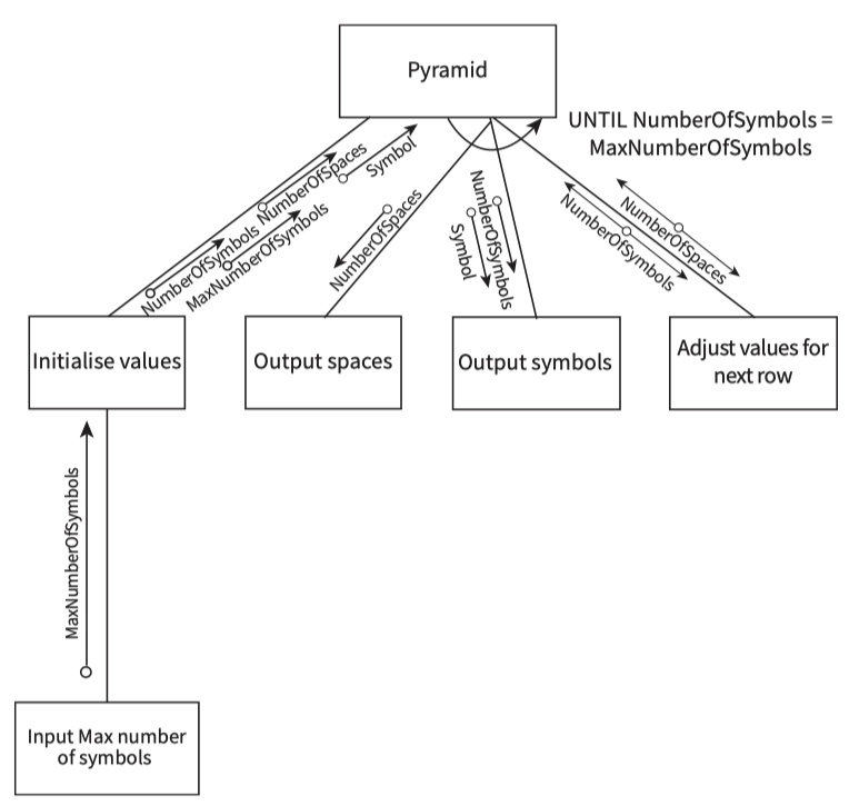
structure charts (2)
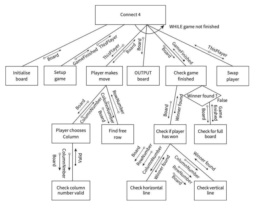
- An arrow with a solid round end
 shows that the value transferred is a flag (a Boolean value)
 - A double-headed arrow
 shows that the variable value is updated within the module.
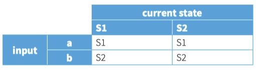
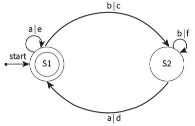
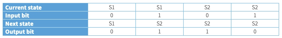
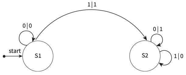
state-transition diagrams
state-transition table
state-transition diagram
state-transition diagram with outputs
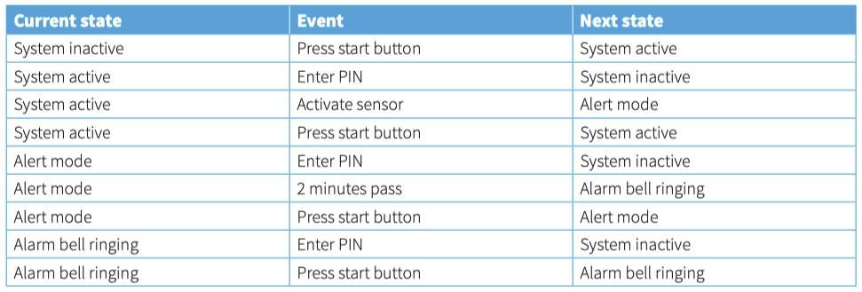
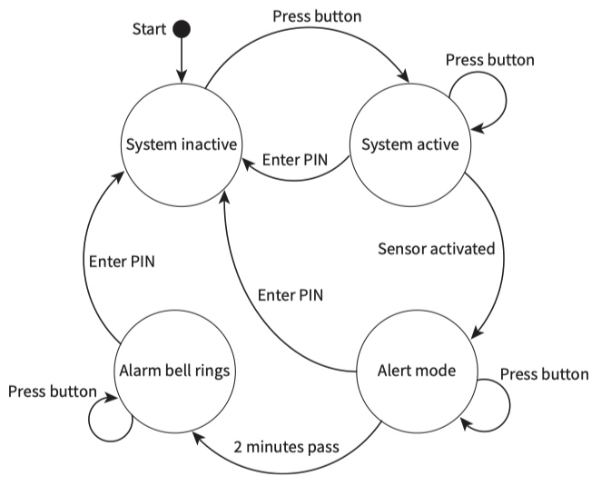
Worked example : Creating a state-transition diagram for an intruder detection system
Description of the system: The system has a battery power supply. The system is activated when the start button is pressed. Pressing the start button when the system is active has no effect. To de-activate the system, the operator must enter a PIN. The system goes into alert mode when a sensor is activated. The system will stay in alert mode for two minutes. If the system has not been de-activated within two minutes an alarm bell will ring.
state-transition table
state-transition diagram
Worked Example:: Creating a state-transition diagram for a two’s complement FSM
state-transition diagram
A finite state machine has been designed that will take as input a positive binary integer, one bit at a time, starting with the least significant bit. The FSM converts the binary integer into the two’s complement negative equivalent. The method to be used is as follows.
1 Output the bits input up to and including the first 1. 2 Output the other bits following this scheme:: 1. For each 1, output a 0. 2. For each 0, output a 1.
state-transition table
测试流程
stub 测试
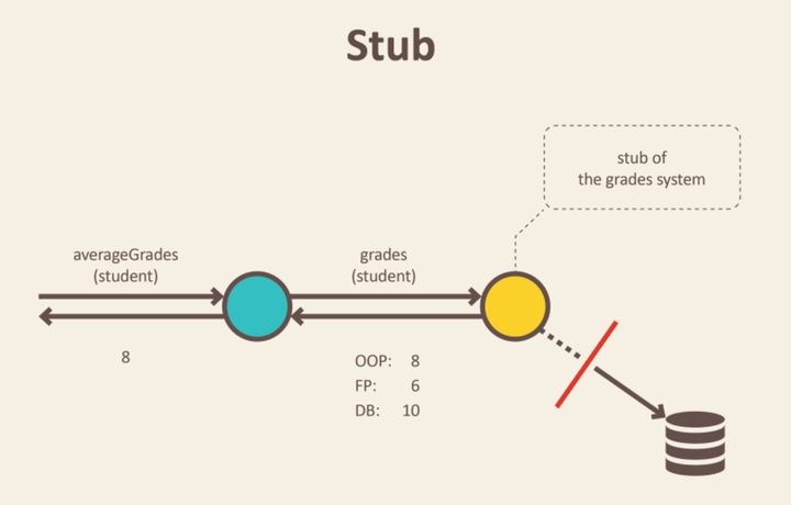
Stub 的典型应用场景即是当某个对象需要从数据库抓取数据时,我们并不需要真实地与数据库进行交互或者像 Fake 那样从内存中抓取数据,而是直接返回预定义好的数据。
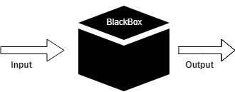
黑盒测试
黑盒测试是一种软件测试技术,它在不查看软件内部结构或编码的情况下检查软件的功能。黑盒测试的主要来源是客户声明的需求规范。
在这种方法中,测试者选择一个函数并给出输入值来检查它的功能,并检查该函数是否给出了预期的输出。如果函数产生正确的输出,则它在测试中通过,否则失败。测试团队将结果报告给开发团队,然后测试下一个功能。完成所有功能测试后,如果出现严重问题,则反馈给开发团队进行修正。
黑盒测试过程:
- 黑盒测试是基于需求的规范,所以从一开始就检查。
- 在第二步中,测试人员通过选择有效和无效的输入值来检查软件是否正确或不正确地处理它们,从而创建正面测试场景和负面测试场景。
- 第三步,测试人员开发各种测试用例,如决策表、所有对测试、等价划分、误差估计、因果图等。
- 第四阶段包括执行所有测试用例。
- 在第五步中,测试人员将预期输出与实际输出进行比较。
- 在第六步也是最后一步,如果软件有任何缺陷,则将其修复并再次测试。
White-box testing
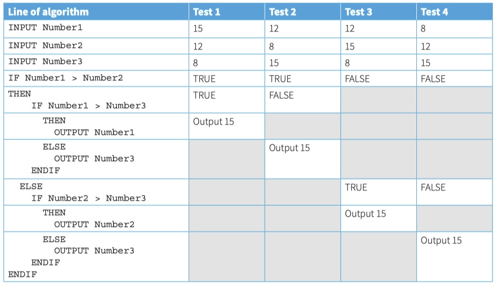
How can we check that code works correctly? We choose suitable test data that checks every path through the code. This is called white-box testing.
worked example:: White-box testing of pseudocode
INPUT Number1
INPUT Number2
INPUT Number3
IF Number1 > Number2
    THEN           // Number1 is bigger
        IF Number1 > Number3
            THEN
                OUTPUT Number1
            ELSE
                OUTPUT Number3
        ENDIF
    ELSE           // Number2 is bigger
        IF Number2 > Number3
            THEN
                OUTPUT Number2
            ELSE
                OUTPUT Number3
        ENDIF
ENDIF
Dry-running an algroithm
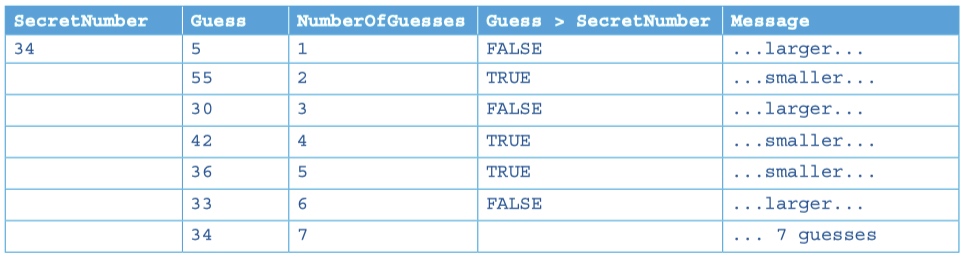
A good way of checking that an algorithm works as intended is to dry-run the algorithm using a trace table and different test data. This is also known as a walk through.
Worked example:: Tracing an algorithm
SecretNumber ← 34
INPUT "Guess a number: " Guess
NumberOfGuesses ← 1
REPEAT
    IF Guess = SecretNumber
        THEN
            OUTPUT "You took ", NumberOfGuesses, " guesses”
        ELSE
            IF Guess > SecretNumber
                THEN
                    INPUT "Guess a smaller number: " Guess
                ELSE
                    INPUT "Guess a larger number: " Guess
            ENDIF
            NumberOfGuesses ← NumberOfGuesses + 1
    ENDIF
UNTIL Guess = SecretNumber
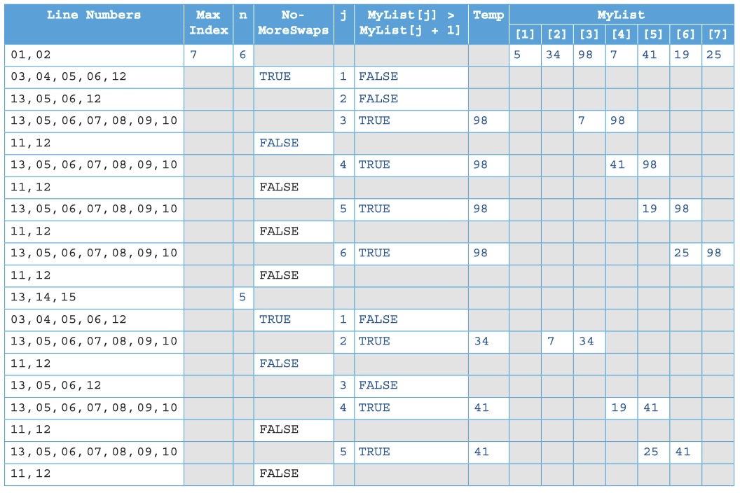
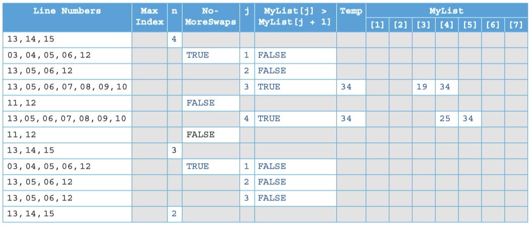
Worked example:: Tracing an algorithm
MaxIndex ← 7
n ← MaxIndex - 1
REPEAT
    NoMoreSwaps ← TRUE
    FOR j ← 1 TO n
        IF MyList[j] > MyList[j + 1]
            THEN
                Temp ← MyList[j]
                MyList[j] ← MyList[j + 1]
                MyList[j + 1] ← Temp
                NoMoreSwaps ← FALSE
        ENDIF
    NEXT j
    n ← n - 1
UNTIL NoMoreSwaps = TRUE
1
Alpha测试
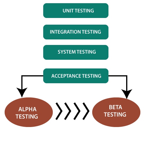
Alpha 测试在组织中进行,并由开发人员方的具有代表性的最终用户组进行测试,有时由独立的测试人员团队进行测试。
Alpha 测试是在内部站点进行的模拟或真实操作测试。它是在单元测试、集成测试等之后进行的。在执行所有测试之后使用 Alpha 测试。
它可以是白盒测试,也可以是黑盒测试,具体取决于要求——特定的实验室环境和此测试所需的实际环境的模拟。
Alpha 测试是用户验收测试。在产品通过测试阶段并准备发布后执行 Alpha 测试。它在 beta 测试之前执行,这也是验收测试的一部分,可以定义为现场测试。在此测试期间,我们可以对软件进行更改以提高其质量和功能。Alpha 测试在开发人员的站点上完成,独立开发人员可以在其中监视和记录用户体验并进行必要的更改以提高性能。
Alpha 测试是测试的最后阶段。Alpha 测试是一种必不可少且流行的测试技术,可帮助团队交付优质且有用的软件。该测试在产品发布之前进行。Alpha 测试可以定义为确保软件按照需求计划运行的第一轮独立测试。
Worked Example